TL/DR
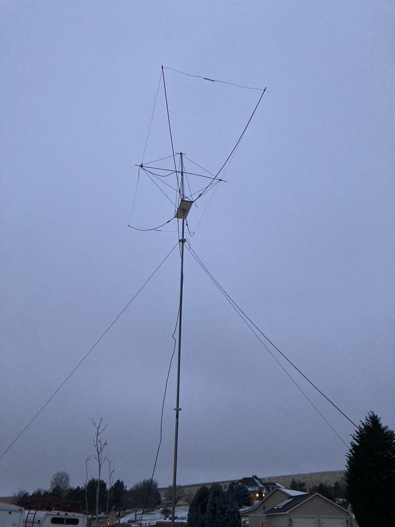
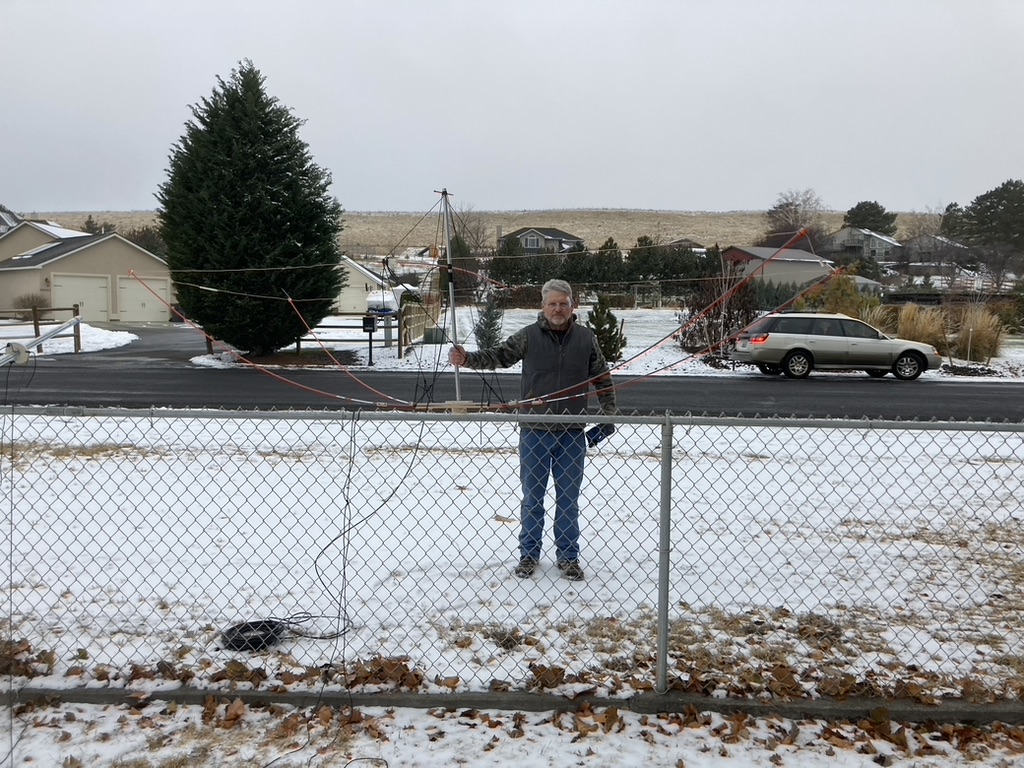
Along with two friends, Mike K7NT and Bob WV7W, I built a 10M Moxon antenna for use in the 2022 ARRL 10M contest. The driven element and reflector are made from 14g stranded wire and are held in their rectangular form by 5/16″ fiberglass driveway marker poles from Home Depot. The central hub is made of plywood. The first, simplest form of the structure was too floppy to support itself, so some improvised supports were made from a discarded painter’s pole and some para-cord. I doubt it would withstand a major windstorm but the result was pleasingly stiff and very lightweight. It is deployed 20′ high and is supported by two 10′ lengths of chain link fence top rail. The antenna’s bearing is adjusted using an “armstrong” rotator– we just ran out in the snow and moved it as needed. Total cost was less than $100.
I’ll give some details of the construction below. Following that I’ll give the results of some simple experiments I performed to gauge the antenna’s behavior.
Design
There are a number of design tools available online, but be careful: they are not all the same, nor are they all accurate. More on this later, but we began by assuming that they all did basically the same thing. We only began looking critically at the tools when the first version of the antenna tuned off the top of the 10m band with a minimum SWR at 30.3 MHz.
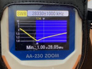
The tool we settled on is Fred Cirera’s (W6BSD) excellent Moxon antenna calculator. The only input parameters required are the desired resonant frequency and the diameter of your antenna wire. We decided on a target frequency of 28.3 MHz in order to favor the CW portion of the band while hoping for an acceptable SWR all the way to the top. We also used as a reference the article “Having a Field Day with the Moxon Rectangle” from the June 2000 edition of QST.
Our first attempt was based on the W4/VP9KF Moxon Antenna Calculator. This produced an antenna that tuned far higher than desired. We found this puzzling. We then noticed that the dimensions varied substantially from those in the QST article. We next tried Fred’s calculator, which produced dimensions that were longer, which would lower the resonant frequency and which matched those in the article very closely. In the end, our antenna resonated right at the bottom of the 10m band, but it was acceptable and we were out of time before the contest began.
Construction
We decided on a mechanical design similar to the 6m Moxon shown on Fred Cirera’s Page. My experience is with woodworking so I thought to make the central hub out of plywood. Bob has a CNC router and a 3-D printer, and he offered to knock these parts out in his garage. The three of us drove over to his house, and a couple hours later we had everything cut out and ready for assembly.
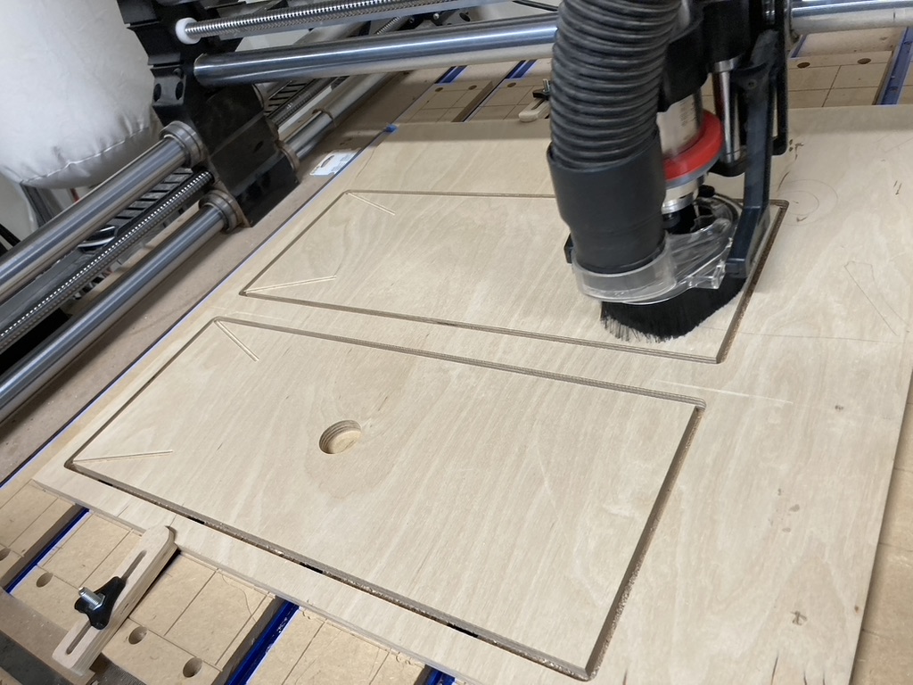
Two plywood plates would sandwich the fiberglass wire support poles. Those poles would be captured in V-grooves located at the corners of the rectangles. The mast would pass through a hole in the center of the bottom plate.
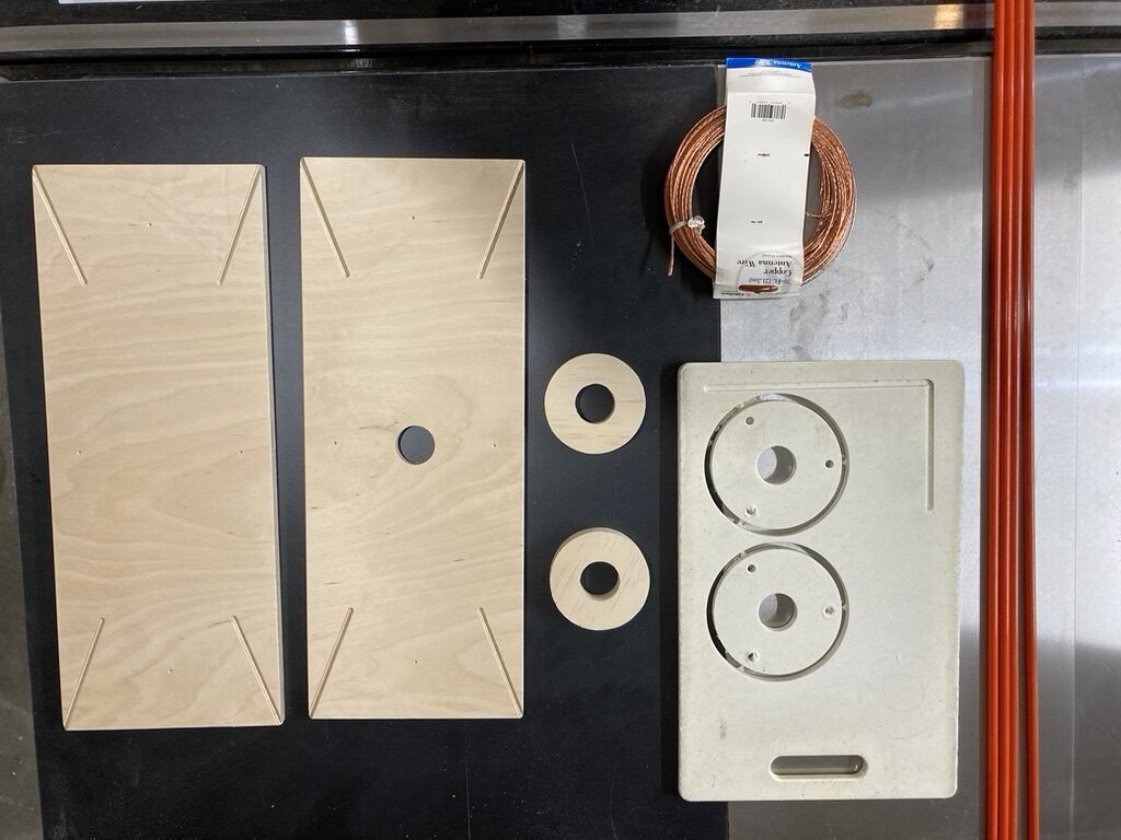
Here are all of the parts, machined and ready for assembly. Steel nut inserts were added to the plates to secure the fiberglass poles. The two plywood rings were glued and screwed to the bottom plate to support the hub and secure it to the mast. At right there are two rings machined out of an old plastic cutting board. These went around the mast and held guy lines. The antenna wire was from Radio Shack and had been following Mike around for decades!
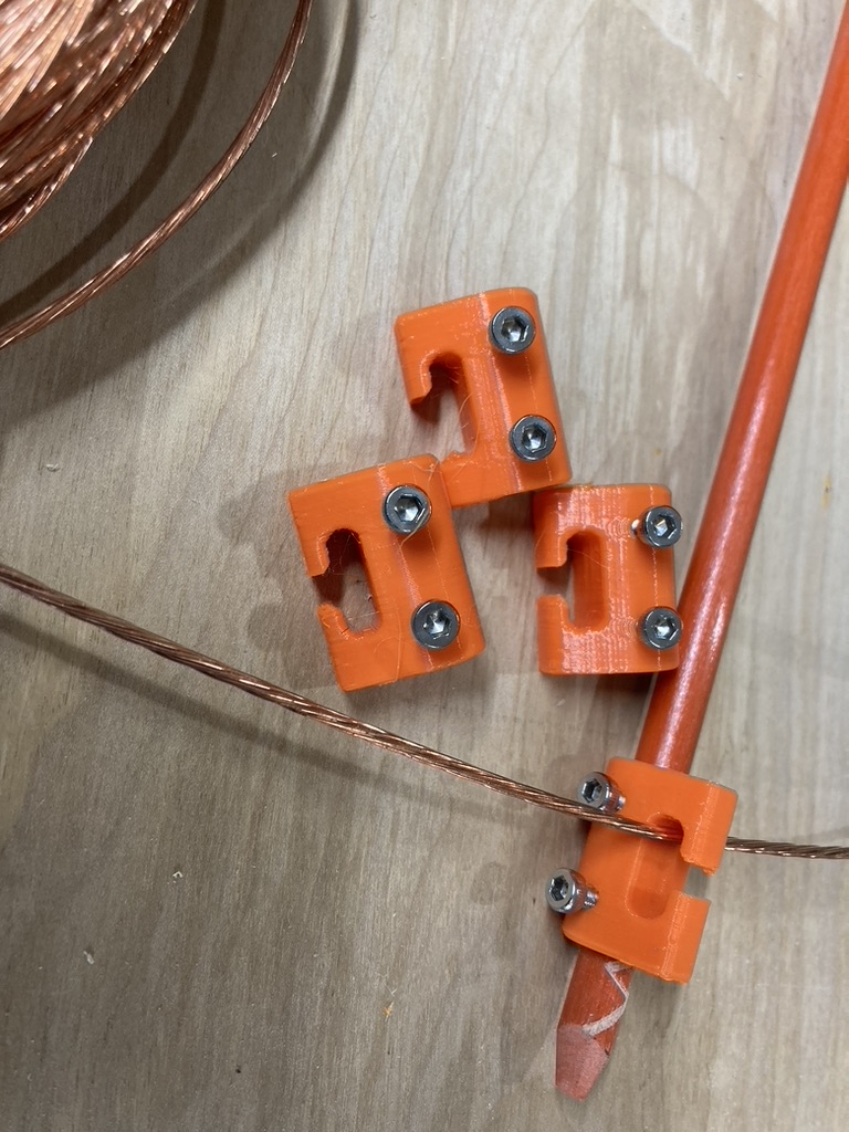
Bob also 3-D printed these nifty clips to capture the antenna wire at the end of the fiberglass poles. We ended up also using zip ties to secure the wire to the clips, which was mainly needed during assembly.
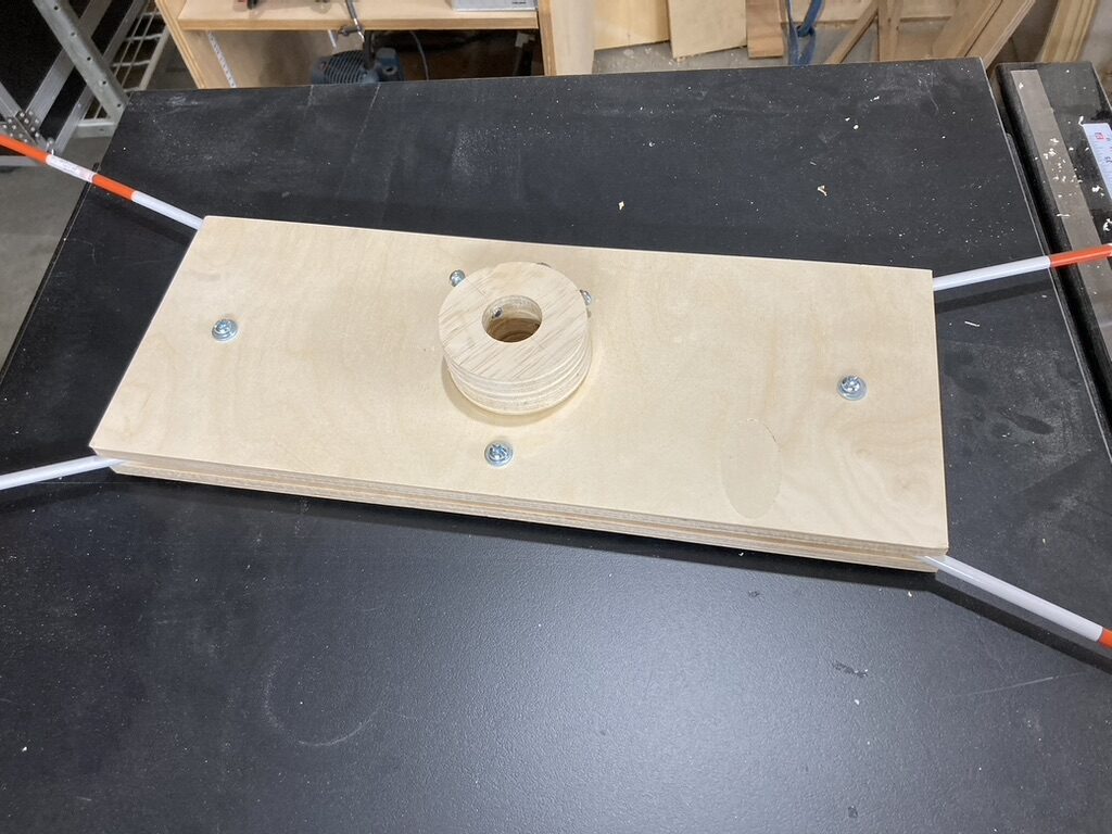
Here is the final hub assembly, upside down and ready for use. You can see two set-screws fitted to the donuts to secure the hub to the mast.
The fiberglass whips were slightly too short for our dimensions and we needed to splice on about a foot to the length of each pole. The whips were also far too bendy to support the wires. I added a length of an old painters pole to sit on top of an extend the mast. About 18″ above the central hub, I drilled holes in the painters pole and added a short length of the same fiberglass rod to support the feed point in the front and the midpoint of the reflector in back. I then started tying paracord to suitable parts of the structure to make lots of triangles. This stiffened up the structure nicely and it still weighs just a few pounds.
Performance
Our first question after getting this thing on the mast and up in the air was how it performed. Mike and Bob both live within 10 miles of me, and our first thought was to have Mike set his station to transmit on 10M WSPR. We could then point the Moxon at, away from, and 90 degrees from a bearing to his house. We expected to observer the strongest gain when pointed at his house, a much weaker signal pointing away, and a weaker still signal with his station in the side nulls. But all signals were roughly the same, and stanger still, all signals were far worse than those captured by my end-fed wire. After scratching my head over night about this, I decided it must be due to the fact that his Grayline Flagpole antenna is vertically polarized the the Moxon is horizontally polarized.
So my next step was to try to find two stations who were transmitting frequently on 10m WSPR. I found two such stations, one in California and one in Ohio, which were roughly 90 degrees apart. Over several hours, I noted the WSPR reports from these stations as I moved the antenna to put them variously forward, backward, and to the side of the Moxon. Although the results vary along with changing propagation, you can indeed see that the signals are strongest in the forward direction, weaker from behind, and much weaker to the sides. The SNR averages were taken over irregularly space intervals of about 30 minutes each. For the station in Ohio, I even switched in my wire antenna at one point.
| Grid | Antenna/relation | SNR |
| EN75 | Moxon side | -7 |
| EN75 | Wire | -3.6 |
| EN75 | Moxon front | -2.3 |
| EN75 | Moxon back | -3.1 |
| EN75 | Moxon front | 1.4 |
| EN75 | Moxon side | -5.9 |
| Grid | Antenna/relation | SNR |
| DM12lw | Moxon side | -14.3 |
| DM12lw | Moxon back | -23.2 |
| DM12lw | Moxon front | -8 |
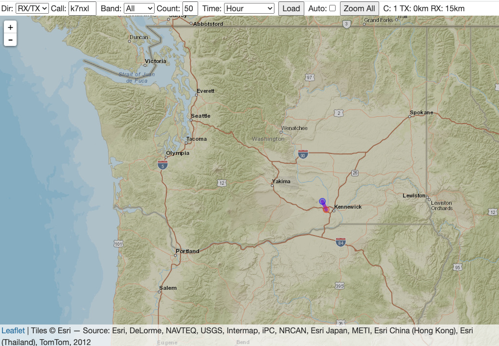
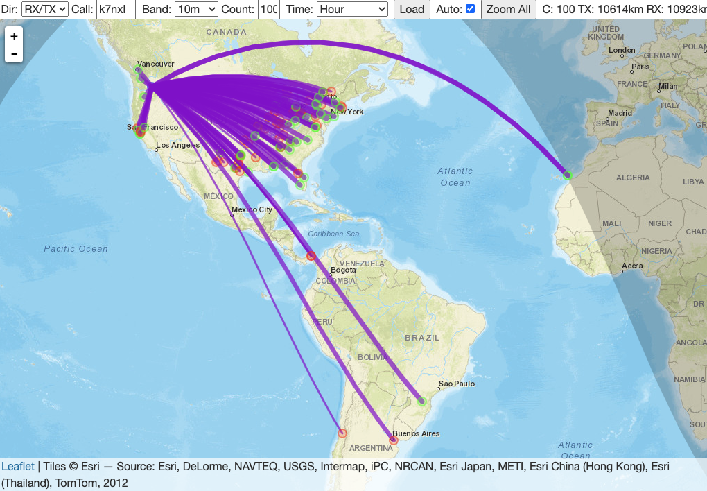
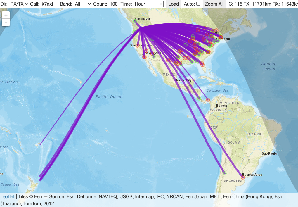
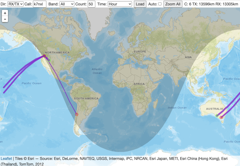
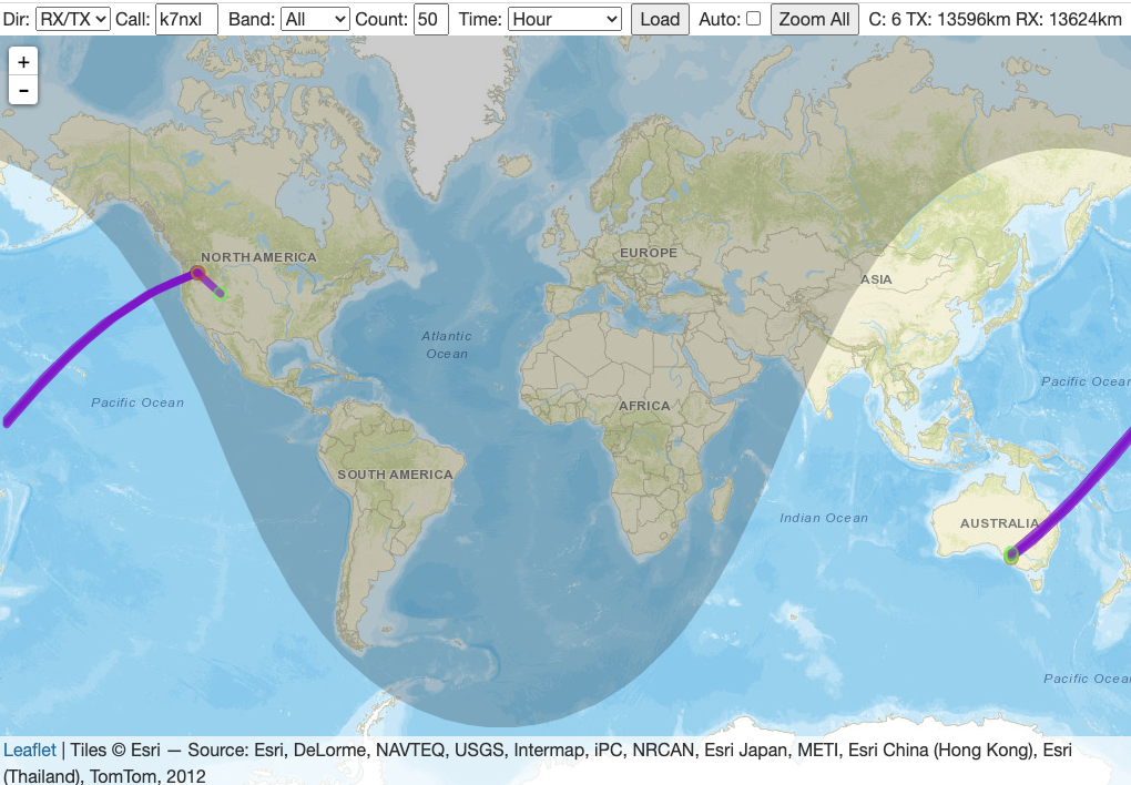
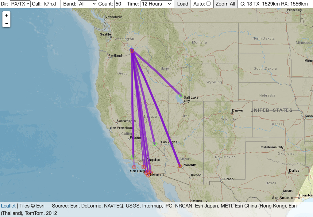
I also started snapping screenshots of WSPR spots just to see how the band evolved over the course of a day. These images show the changing conditions from just before until just after sunset local time.